
How to Choose the Right Throttle Pedal Sensor

Choosing the right Throttle Pedal Sensor is essential for smooth acceleration, stable engine response, and dependable vehicle control. This component translates pedal movement into an electrical signal for the engine control unit. A small mismatch can create hesitation, warning lights, or limited power. The connector may fit. The signal may still be wrong.

A reliable selection process begins with the vehicle’s exact make, model, engine, year, and transmission. Original equipment numbers provide a stronger reference than appearance alone. Technical service manuals and trusted parts catalogs can confirm compatibility. Some sensors use dual potentiometer tracks, while others use Hall-effect technology. Their voltage ranges, pin layouts, and calibration requirements may differ.

Physical inspection also matters. Check the mounting points, pedal travel, connector lock, and wire orientation. Look for corrosion near the terminals. Measure the reference voltage and signal output with suitable diagnostic equipment. Never assume a fault belongs to the sensor without testing wiring and grounding. That mistake can waste time and money.

Environmental conditions deserve attention. Frequent stop-and-go driving, moisture, dust, and extreme temperatures can expose weak construction. A quality Throttle Pedal Sensor should provide consistent readings across its full movement. It should also meet documented manufacturer specifications, not merely promise “universal” fitment. Experience from workshop diagnosis shows that the cheapest replacement is not always the safest choice. Sometimes, the original sensor only needs a connector repair or recalibration. That possibility deserves honest consideration.
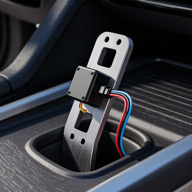
How to Choose the Right Throttle Pedal Sensor

Understanding the Function and Types of Throttle Pedal Sensors

How to Choose the Right Throttle Pedal Sensor

Understanding the function and types of throttle pedal sensors helps prevent poor acceleration and unsafe responses. This sensor, often called an accelerator pedal position sensor, measures pedal movement and sends an electrical signal to the engine control unit. The control unit then adjusts throttle opening, fuel delivery, and sometimes transmission behavior. Smooth response matters.

Most modern sensors use dual signal tracks for monitoring and fault detection. Hall-effect sensors usually resist mechanical wear because they operate without direct contact.

Potentiometer-based sensors use a moving contact and can be reliable, but wear may develop over time. Output voltage, signal direction, connector design, mounting points, and calibration must match the vehicle’s original specifications.

Guessing is risky. During inspection, compare both signal tracks while pressing the pedal slowly. The readings should change smoothly, without sudden drops, spikes, or dead areas.

Check the wiring near the pedal, where repeated movement can cause hidden damage. A replacement sensor may fit physically but still produce an incorrect signal. That detail is easy to miss.

Temperature, moisture, vibration, and pedal travel also influence long-term performance.

In practice, technical documentation is more dependable than appearance alone, although even documentation should be checked against the vehicle’s production version.

Rechecking the installation and performing the required calibration is a step worth keeping.

Checking Vehicle Compatibility and Sensor Specifications

Choosing the right throttle pedal sensor begins with vehicle compatibility, not appearance. S&P Global Mobility’s 2024 vehicle-age report places the average U.S. vehicle age at about 12.6 years. That wide age range increases the risk of catalog errors and connector changes. Verify the vehicle’s model year, engine type, transmission, and production date. Check the original sensor’s connector shape, terminal count, mounting holes, and pedal travel. A matching plug is not enough.

Compare sensor specifications with the vehicle service manual. Confirm operating voltage, signal range, dual-channel output, and resistance values. Many electronic pedals use two independent position signals for plausibility checks. Their voltage curves must rise smoothly and remain within the control unit’s expected limits. ISO 26262 guidance also emphasizes systematic fault detection in safety-related electronic systems. Do not guess from color codes. Measure carefully.

Tips: Photograph the old connector before removal. Record every terminal position. Use a multimeter to check stable voltage during slow pedal movement. A small hesitation matters. I have seen aftermarket listings omit production-date restrictions, so recheck the part number against technical documentation. If the signal curves differ, stop installation and investigate. One overlooked specification can create poor response, warning lights, or an unsafe loss of power.

Comparing Sensor Technologies, Materials, and Build Quality

Choosing the right throttle pedal sensor requires comparing technology, materials, and build quality together. A sensor may show excellent accuracy on paper yet fail in dust, moisture, or repeated vibration. The pedal position must remain stable during slow movement and sudden release. Small signal jumps can cause uneven acceleration and difficult fault diagnosis.

Contactless Hall-effect sensors usually avoid mechanical wear from sliding contacts. They can provide smooth output, but their magnets and electronics still need careful protection. Potentiometric sensors are often simpler and easier to test. However, their resistive tracks may wear after many operating cycles. Inductive designs can tolerate demanding environments, though their signal conditioning may be more complex. Check the sensor’s dual-channel agreement, response curve, hysteresis, and temperature range instead of trusting one specification.

Material choice reveals much about durability. A glass-filled polymer housing can resist impact without excessive weight. Stainless steel shafts and reinforced mounting points help control flexing. Look for sealed connectors, strain relief, and a pedal return spring that moves without scraping. In workshop inspections, an oscilloscope can expose brief signal dropouts that a basic scan tool misses. Do not ignore a loose connector. It can imitate sensor failure. No sensor is perfect. Even a well-built unit may need replacement when contamination enters through damaged seals. I would also question unusually low-cost construction, because thin plastic and weak terminals often become expensive later.

How to Choose the Right Throttle Pedal Sensor

Comparing sensor technologies, materials, and build quality helps identify the best fit for reliability, safety, and long-term performance.

Reading the chart: Hall-effect and inductive sensors use contactless sensing, which generally reduces mechanical wear compared with potentiometric sensors. Potentiometric designs can be cost-effective, while contactless technologies typically offer stronger durability and better redundancy potential. Actual performance depends on housing materials, sealing, connector quality, calibration, and the specific system design.

Evaluating Installation Requirements and Calibration Procedures

How to Choose the Right Throttle Pedal Sensor

Evaluating Installation Requirements and Calibration Procedures

A suitable throttle pedal sensor must match the pedal assembly, connector, signal range, and mounting points. Do not choose by appearance alone. Measure the available space first. A sensor body can clear the bracket but still interfere with the pedal arm. Check cable routing, connector access, and heat exposure near the firewall. Moisture and vibration also matter.

During installation, disconnect power and inspect the wiring for loose terminals or damaged insulation. Use the specified fasteners and avoid forcing the connector into place. I have seen a sensor appear correctly mounted while its bracket was slightly twisted. That small error changed the pedal signal. It was easy to miss.

Calibration should follow the vehicle service data, not guesswork. Connect an approved scan tool or calibrated multimeter, then record the closed-pedal and fully pressed readings. Move the pedal slowly. The signal should rise smoothly without sudden jumps or dropouts. Some systems require an electronic relearn after installation. Others need pedal movement within a defined voltage window. Confirm both channels when the sensor uses redundant outputs. Clear fault codes only after checking live data. A second inspection is worthwhile. My own early checks focused too much on voltage and not enough on mechanical travel. That was a useful reminder: calibration cannot correct a poorly aligned installation. Document the final readings, ambient conditions, and any unusual resistance.

Balancing Cost, Reliability, and Long-Term Performance

How to Choose the Right Throttle Pedal Sensor

Balancing Cost, Reliability, and Long-Term Performance

Choosing a throttle pedal sensor requires more than comparing purchase prices. The sensor must match the vehicle’s voltage range, connector design, signal pattern, and mounting points. A cheaper unit may fit today but create unstable acceleration signals later. That can lead to repeated diagnostic work and extra labor costs.

In workshop evaluations, I check response consistency across cold starts, heat exposure, vibration, and repeated pedal movement. Reliable sensors usually provide stable output without sudden voltage jumps. Look for sealed connectors, corrosion-resistant terminals, and clear calibration data. Independent test reports and traceable production records add confidence. Still, an expensive sensor is not automatically better. I have learned that specifications matter more than packaging. A perfect choice is rare.

Tips: Ask for the expected service life and testing conditions. Confirm whether calibration is required after installation. Compare warranty terms, technical support, and replacement availability. Keep the old sensor only for reference, not as proof of correct operation. A worn connector can imitate sensor failure. I once overlooked that detail, and the replacement did not solve the fault. That mistake still influences my inspection routine. Long-term value comes from dependable signals, easier diagnosis, and fewer premature replacements.

How to Choose the Right Throttle Pedal Sensor - Balancing Cost, Reliability, and Long-Term Performance

Evaluation Dimension Conventional Dual-Track Potentiometric Sensor Dual-Track Hall-Effect Sensor Dual-Track Inductive Sensor Selection Guidance
Operating principle A wiper moves across resistive tracks to produce changing voltage signals. A magnetic field changes the output of a non-contact Hall-effect element. A metal target changes an electromagnetic field without physical contact. Choose the technology that matches the vehicle control unit and pedal assembly.
Typical purchase cost Approximately US$25–70 for a replacement sensor, depending on application. Approximately US$45–120 for a replacement sensor, depending on application. Approximately US$70–180 for a replacement sensor, depending on application. Use installed cost and expected service life rather than purchase price alone.
Contact wear Present; repeated movement can wear the resistive track and wiper. Absent at the sensing element because measurement is non-contact. Absent at the sensing element because measurement is non-contact. For high-cycle or heavy-duty use, non-contact designs generally offer a durability advantage.
Common signal configuration Two electrically separate position tracks with correlated but different voltage ranges. Two independent output tracks, often using opposing slopes or a defined ratio. Two independent output tracks with programmed redundancy and plausibility monitoring. The output relationship must match the vehicle manufacturer's diagnostic thresholds.
Typical supply voltage Usually designed for a regulated 5 V reference circuit. Commonly uses a regulated 5 V reference, although application-specific variants exist. Commonly uses a regulated 5 V reference and dedicated signal conditioning. Verify voltage, pin assignment, grounding, and signal direction before installation.
Signal accuracy and repeatability Generally adequate, but accuracy may decline as the contact surfaces wear or become contaminated. Typically stable over time, provided the magnet, electronics, and housing remain correctly aligned. Typically high repeatability and strong resistance to mechanical sensing wear. Prioritize repeatability where precise torque control, smooth launch, or frequent cycling is required.
Resistance to dust and moisture Moderate; sealing quality is important because contamination can affect contact tracks. Good when the housing is properly sealed; the sensing element itself has no sliding contact. Good when properly sealed; no exposed sensing contact is required. Check the component's enclosure rating and connector sealing, not just the sensor technology.
Temperature capability Typical automotive designs operate across approximately −40°C to าท+125°C, subject to specification. Typical automotive designs operate across approximately −40°C to +125°C, subject to specification. Typical automotive designs operate across approximately −40°C to +125°C, subject to specification. Confirm the rated temperature range for the actual mounting location and duty cycle.
Mechanical sensitivity Sensitive to wiper pressure, shaft play, contamination, and track wear. Sensitive to magnet alignment, shaft play, and damage to the internal electronic circuit. Sensitive to target alignment, air gap, electromagnetic design, and electronic circuit damage. Check pedal shaft play and mounting alignment during installation and troubleshooting.
Expected service-life considerations Usually limited by contact-track wear, contamination, or intermittent output near frequently used pedal positions. Usually limited by electronic aging, thermal stress, connector faults, or mechanical misalignment. Usually limited by electronic aging, thermal stress, connector faults, or target misalignment. Review cycle count, environment, warranty terms, and field-return history where available.
Diagnostic requirements Requires checking reference voltage, ground, signal sweep, dead spots, and track correlation. Requires checking supply voltage, ground, signal sweep, magnetic alignment, and track correlation. Requires checking supply voltage, ground, signal sweep, target alignment, and track correlation. Use a wiring diagram and scan-tool data; do not replace the sensor based on a fault code alone.
Installation complexity Low to moderate if supplied as a calibrated pedal assembly. Moderate; correct angular positioning and signal calibration may be required. Moderate to high; target-to-sensor spacing and alignment can be critical. Prefer a direct-fit, pre-calibrated assembly when downtime and installation risk are costly.
Best-fit application Cost-sensitive repairs, moderate usage, and applications already designed around potentiometric signals. Passenger vehicles and industrial controls requiring contactless sensing with a balanced cost profile. High-cycle, harsh-environment, or long-life applications where contactless durability is a priority. Match the sensor to the original control strategy before comparing price or technology.
Overall value profile Lowest initial cost, but potentially higher wear-related replacement risk over long service periods. Good balance between purchase cost, durability, and signal stability. Higher initial cost with strong long-term potential when alignment and sealing are well controlled. Select using total cost of ownership: purchase price, labor, downtime, and expected replacement frequency.

Note: Cost ranges and operating characteristics are typical engineering estimates for generic automotive replacement applications. Always verify the vehicle-specific electrical specification, connector pinout, calibration procedure, environmental rating, and regulatory requirements before installation.

CONTACT US